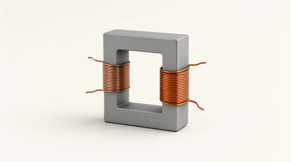
About this experiment
A transformer changes alternating voltage by sharing a changing magnetic flux between two windings. Change the turns ratio and load to see voltage and current trade off while power is conserved. All readings are RMS values for sinusoidal AC; the winding sketch represents turns rather than drawing every individual turn.
Learning goals
- Investigate how secondary turns affects secondary rms voltage while controlling the other variables.
- Use the graph and numerical readings to test a prediction.
- Explain the physical assumptions and where this model stops applying.
How to use it
- 1Use 400 primary turns, 200 secondary turns, 24 V and 100 Ω. Check 12 V and 0.12 A at the secondary.
- 2Save the curve and double primary turns. Compare the slope.
- 3Keep turns fixed and halve load resistance. Which voltages stay constant and which currents double?
- 4Set equal turns. Check that primary and secondary currents match.
The model
Assumptions
- The input is sinusoidal AC and every voltage and current reading is RMS. Coupling is perfect and magnetising current is ignored.
- There are no winding losses, core losses, saturation or source limits. Large predicted powers are ideal extrapolations, not equipment ratings.
Try this in class
- Q1Why is secondary current larger than primary current in a step-down transformer?
- Q2What turns ratio gives 6 V from 24 V in this ideal model?
Frequently asked questions
Would this transformer work with steady DC?
No. Steady DC does not maintain a changing core flux. The voltage ratio model here assumes alternating excitation.
Does increasing the voltage create energy?
No. The ideal transformer conserves power. Output current and input current adjust with the turns ratio and connected load.